On automotive and construction machinery assembly lines, small metal components such as pins, sleeves, rollers and chain plates have long required manual picking from bins and placement onto secondary positioning fixtures. Workers face fatigue caused by oil-film reflections and repetitive alignment work, while having to keep up with the line cycle time.
A 3D vision feeding system recently deployed at an equipment manufacturing workshop in East China adopts a “one camera + mobile module” architecture to cover six feeding stations and 16 workpiece variants simultaneously, automating this process with robots.
Multiple Varieties, Oil Film Reflections, Precision and Cycle Time
The line is challenged on two fronts. It processes two categories of metal workpieces totaling 16 variants: bar stock including pins, sleeves, rollers and joint pins, with outer diameters ranging from 21 mm to 72 mm; plate stock including inner and outer chain plates and hopper connection plates, with maximum dimensions up to 245 mm × 180 mm.
Workpieces are loaded uniformly into standard bins sized 1200 mm × 800 mm × 400 mm, stacked neatly. Each bin holds workpieces of the same part number with consistent orientation.
Several on-site conditions created challenges for the vision system: workpieces carry a thin layer of anti-rust oil, resulting in prominent reflections on metal surfaces. Bins are delivered by AGVs or forklifts with placement deviation up to 100 mm. The gripper uses an electromagnetic suction cup with V-shaped grooves on its bottom. The vision system must output workpiece pose data to ensure stable suction, while maintaining a unilateral clearance of no less than 3 mm once the part is placed on the secondary positioning fixture.
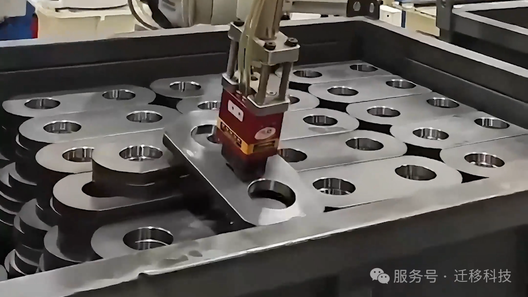
Hard performance requirements specified by the customer: minimum recognition rate of 99.9%. For bar stock, single-part image capture and computation ≤5 seconds; for plate stock ≤6 seconds.
Camera Mounted on Mobile Module — One Unit Covers Multiple Bins
Instead of the conventional layout with one fixed camera above each bin, the project mounts the Epic Eye Laser L V2S 3D industrial camera on a transverse mobile module, which travels to scan different bins.
Once a bin is in position, the control system sends the current workpiece model to the vision system. The camera moves roughly 1500 mm above the bin to capture a scan, calculates the gripping pose of the top-layer workpieces in a single pass, then transmits coordinates to the six-axis robot over TCP/IP.
The robot picks workpieces using the electromagnetic suction cup and places them onto the secondary positioning fixture. This cycle repeats until the bin is empty; the camera then moves to the next bin. Once an empty-bin signal is fed back, the system prompts operators or the AGV to replace the bin.
Key benefits of this layout:
Multiple stations share one camera to cut hardware costs. The camera’s longitudinal axis is parallel to the length of bar stock, enabling one field of view to cover the full bin. The mobile module delivers positioning accuracy of 0.1 mm. Combined with vision alignment, the software compensates for bin placement deviations at the hundred-millimeter level.
Laser Galvo Camera + Graphical Vision Software
The vision hardware deployed is Transfer Technology’s Epic Eye Laser L V2S industrial 3D camera. Designed for medium-to-long range, large field-of-view applications, it leverages blue laser galvo scanning paired with binocular vision imaging. It outputs stable point clouds over a working distance of 1200 mm–3000 mm and performs reliably against dark, reflective metal parts and variable workshop ambient lighting.
The vision software used is Epic Pro. It features a graphical, flow-based interface. Engineers can configure camera connection, hand‑eye calibration, gripping parameters and communication interfaces via drag-and-drop programming. It supports both eye‑to‑hand and eye‑in‑hand configurations and connects to mainstream industrial robots and PLCs. In this project, it communicates with the robot controller over TCP/IP.
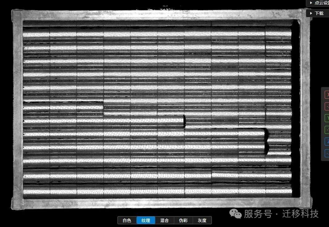
For the 16 workpiece variants, our engineering team imported workpiece models on-site, built vision algorithm graphs and completed station-by-station commissioning. Customer engineers can add new variants independently following training procedures, with remote technical support from Transfer Technology.
From "Hard-to-Automate Manual Tasks" to "Fast Part Changeover"
The system achieves a single-workpiece vision cycle time of ≤5 seconds for bar stock and ≤6 seconds for plate stock, with a minimum recognition rate of 99.9%. Three tangible improvements on the workshop floor:
- 1.Manual task replacement: Robots take over repetitive piece picking and alignment work, freeing operators from labor-intensive handling.
- 1.Flexible part changeover: A single vision system handles all 16 workpiece variants. Part switching is triggered by signals from the control system with no on-site recalibration required.
- 1.Simplified deployment: Sharing one camera and mobile module across multiple stations reduces the total camera count and mounting framework work compared with fixed per-station camera installations.
Notably, the solution does not differentiate between large/small ends for bar stock or front/back sides for plate stock. The vision system only outputs pose guidance; downstream secondary positioning fixtures handle subsequent posture correction. This architecture keeps vision algorithms focused and shortens on-site commissioning time.
Replicable Engineering Insights
For manufacturers planning assembly-line feeding automation retrofits, this case delivers three practical takeaways:
- 1.Clearly define the scope of the vision system. As demonstrated in this project, delegating front/back orientation and end identification to downstream fixtures while limiting vision to pose guidance greatly cuts algorithm commissioning time.
- 1.For large bins and multi-station setups, evaluate mobile camera layouts first. When bins contain fixed part types with consistent workpiece orientation, a camera travelling on a module reduces hardware expenditure versus fixed cameras above every bin and simplifies future station expansion.
- 1.When working with reflective, oil-coated metal workpieces, validate point cloud quality at the product selection phase. Blue laser galvo scanning performs well under such conditions. Still, trial scans using real workpieces are recommended at the early project stage.
From pins and sleeves to chain plates and connection plates, 3D vision is transforming assembly-line feeding from labor-intensive manual operation to flexible automation. This methodology delivers replicable engineering value for multi-variant, small-to-medium batch metal component production lines.
Start Your
3D Vision Journey
Whether it's product selection, custom solutions, or technical support — our expert team is always ready to help.
Service Hotline
4000-191-161
Business Email
marketing@qianyi.ai
19110438869
Office Locations
Beijing HQ
Floor 14, Building 2, Weilai Park South Zone, Changping District, Beijing